GPIOs
Here a GPIO table for the ESP32 module used in the PCB:
| GPIO | Function | Description |
|---|---|---|
| 3 | Thermistor VCC | Switch to provide NTC thermistor VCC only when measuring |
| 4 | Display | Display power on/off |
| 5 | Display RX | Display UART data line |
| 6 | Display TX | Display UART data line |
| 7 | Buzzer | Buzzer PWM |
| 8 | Daughter | |
| 9 | Thermistor ADC | Measurement PIN for the Thermistor |
| 10 | Header | wired but not used |
| 11 | Relay | Relay #1 |
| 12 | Relay | Relay #2 |
| 13 | Header | wired but not used |
| 14 | Daughter | |
| 15 | Daughter | |
| 16 | LD2410 | Presence sensor power cutoff |
| 17 | LD2410 | Presence sensor RX |
| 18 | LD2410 | Presence sensor TX |
| 35 | Microphone | i2c mic WS |
| 36 | Microphone | i2c mic SD |
| 37 | Microphone | i2c mic SCK |
| 38 | Microphone | i2c mic SCK |
| 41 | Switch | right switch |
| 42 | Switch | left switch |
| 21 | Daughter | |
| 47 | Daughter | |
| 48 | Daughter |
Basically all the useable GPIOs are being used. Some of them are being allocated for the daughter board. And 2 of them for the 2.0mm pitch header.
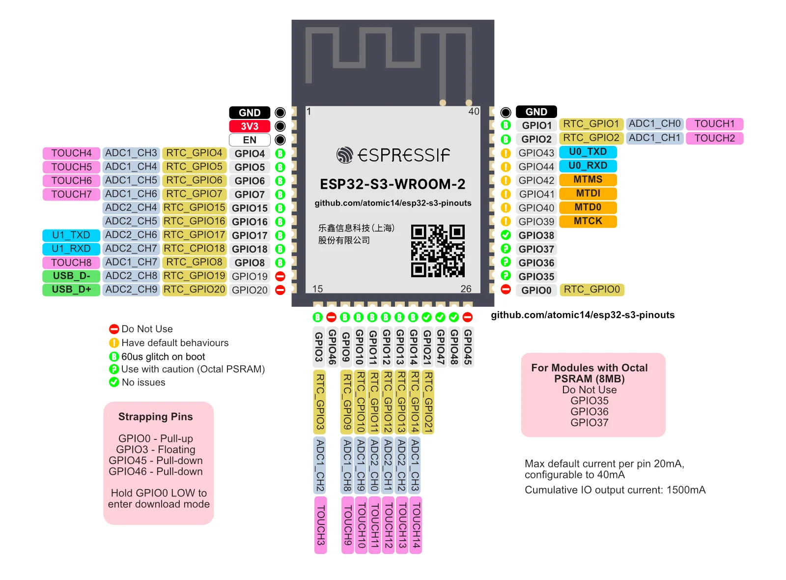
Here below a pinout reference taken from atomic14's repository